1 kW 50 MHz LOW-PASS FILTER
![]() 29-jun-2020
29-jun-2020
INTRODUCTION
To suppress unwanted harmonics, it is recommended to switch a low-pass filter (LPF or low-pass filter) behind a 6-meter output stage. This is especially true for semiconductor amplifiers with a broadband circuit at the output.
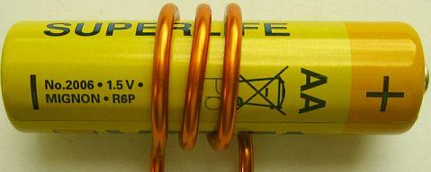
COIL WITH DIAMETER AA BATTERY
 |
|
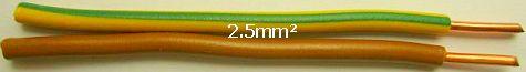
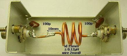
The coils are made of (approximately) 2 mm thick wire. Suited (fig») are brown or yellow-green 2.5 mm² installation wire without insulation. You can use an AA battery for («fig) the coil shape.
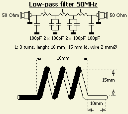
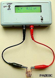
This type is present in almost every household, so that a DIYer does not have to search for a drill, tube or pipe with a suitable diameter. Three windings are applied, which then relax to an inner diameter of 15 mm. The inductance of the coil with on both sides 10 mm long wire ends, is close to 0.12 μH (also PAØEBC's findings).
CAPACITOR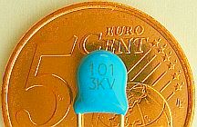
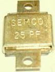
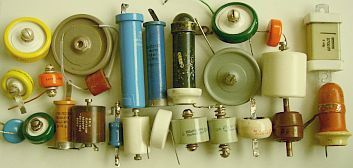
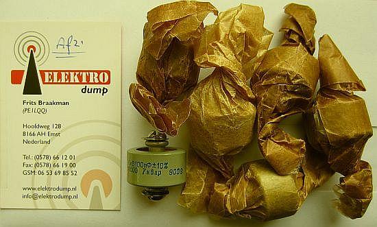
The used capacitors have a capacitance of 100 pF; a common standard value for high voltages. Up to a few hundred watts UNELCO/SEMCO types («fig) with one or two tags are well suited. With lower power (fig»), "ordinary" ceramic disc capacitors are also usable.
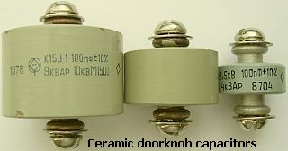
For an output power of max 100 W, the transmitting types shown below are not required. Of course you can opt for "doorknob capacitors" or ton capacitors, at least if you agree with the price. If so working with QRO is no problem.
|
|
|
In the Netherlands, Elektrodump http://www.elektrodump.nl has a stock of such capacitors. They sells small quantity for a fair price.
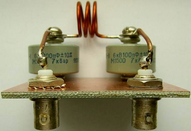
TEST 3-POOL FILTER
|
|
|
|
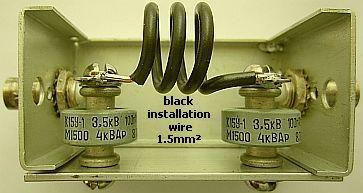
A next experiment served to test a coil of black 1.5 mm² insulated wire. It was also made with the help of an AA battery and had to be slightly stretched for SWR = 1.
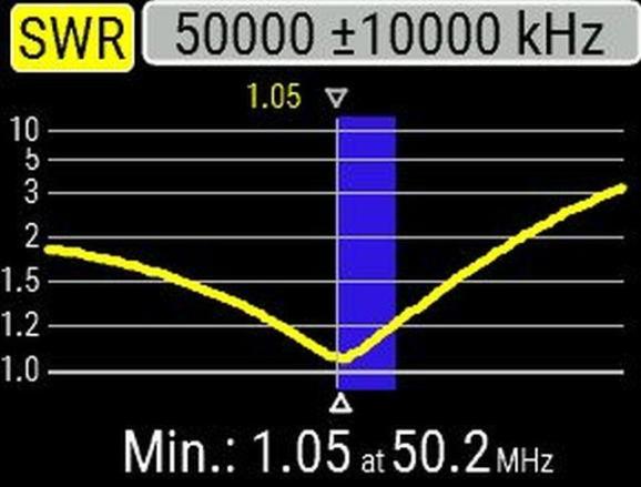
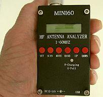
Test with a RigExpert AA-239 ZOOM analyser.
TEST LPF
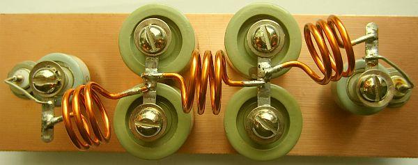
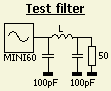
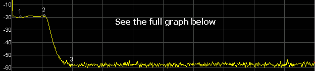
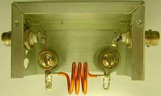
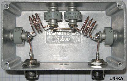
With my limited stock of ton capacitors (fig») a 7-pole filter was provisionally assembled to test the system, because those caps were intended for another project. The aforementioned antenna analyzer and a HP141T were used for the test.
To my surprise, nothing had to be adjusted, because with every change it got worse. Apparently the coils were well tailored. Due to their comparatively large mutual distance, they did not appear to influence each other appreciably. There are more LPF'ers built by me and I have not found a remarkable advantage of screened compartiments.
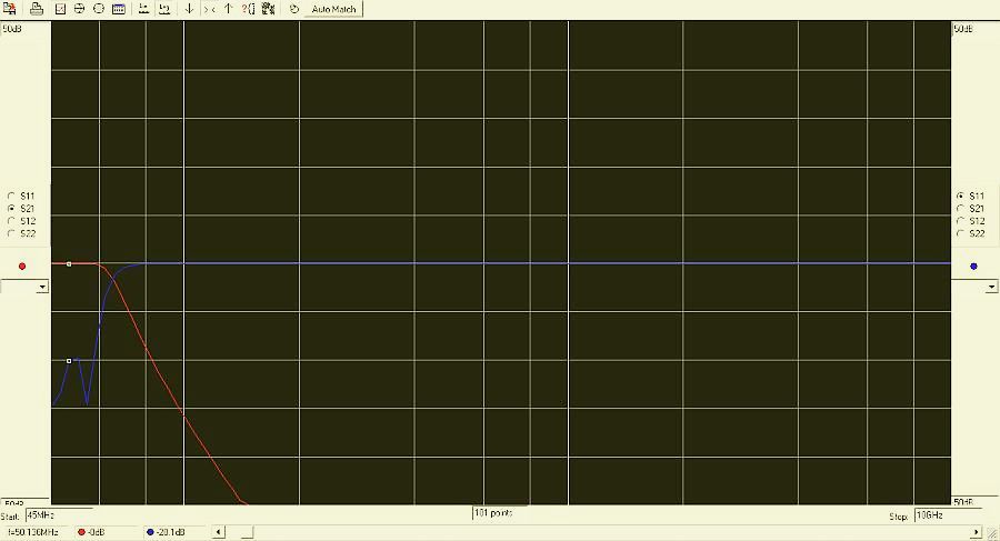
When I came into possession of a DSA815-TG spectrum analyzer, the filter was measured again.
ADJUSTMENT
If necessary, adjust as follows: load the filter at one side with 50 Ohm and supply the signal via a SWR meter on the other side. By pressing or pulling the coils, arrange SWR as low as possible in the center of the band. Then swap input and output and repeat the procedure, continues until a similar result is obtained on both sides.
ON7RA
 |
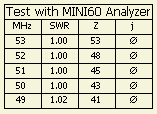
| ON7RA has built a 5-pole filter based on this article and did a simulation with the RFSim99 program (unknown to me). He does not have the equipment for a 100% good adjustment, but with the previously mentioned practical method, everything seems to be work well. SWR = 1 with 10 Watts and an induction-free 50 Ohm/250 W resistor, with 100 Watts SWR = 1.1 and when reversing in and output SWR = 1.2 |
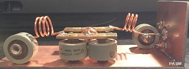
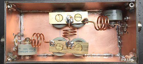
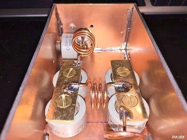
PA1RF
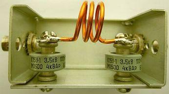
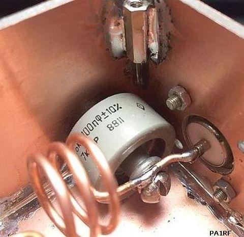
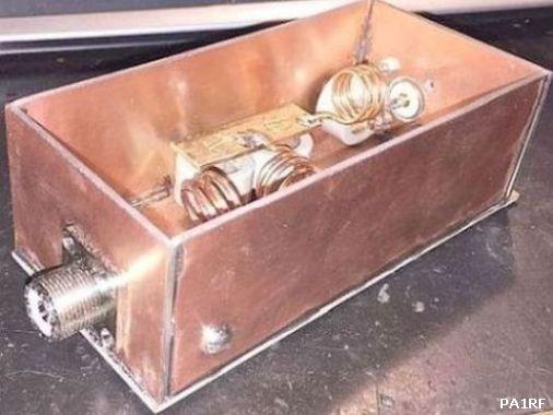
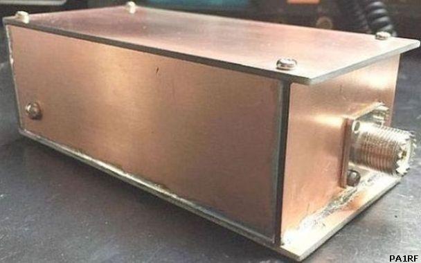
PA1RF had previously built my HF LPF and later this 50 MHz LPF because he still had epoxy material and brass strip in stock. In addition, the required capacitors had already been purchased on a ham flea-market.
 |
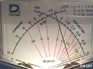 |
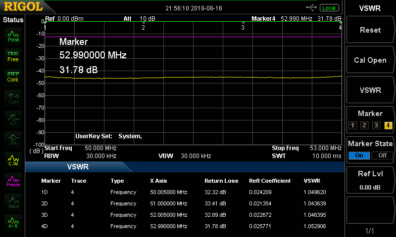
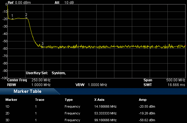
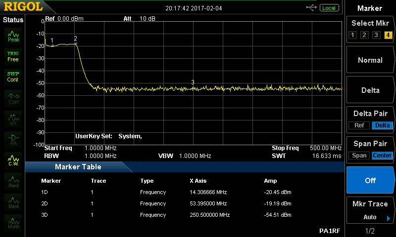
According to him the filter works perfect and he did not have to change the coils after assembling because the SWR was good. The filter is measured with a RIGOL DSA 815 spectrum analyzer (9 kHz - 1.5 GHz), see the images.
![]()